- 您现在的位置:买卖IC网 > Sheet目录250 > SEN02G64C4BF2SA-30WR (Swissbit NA Inc)DRAM DDR2 2GB 200-SODIMM
Data Sheet
Rev.1.3
09.11.2010
EEPROM using the standard I C protocol. This nonvolatile storage device contains 256 bytes. The first 128 bytes
This Swissbit module is an industry standard 200-pin 8-byte DDR2 SDRAM Small Outline Dual-In-line Memory
Module (SO-DIMM) which is organized as x64 high speed CMOS memory arrays. The module uses internally
configured octal-bank DDR2 SDRAM devices. The module uses double data rate architecture to achieve high-
speed operation. DDR2 SDRAM modules operate from a differential clock (CK and CK#). READ and WRITE
accesses to a DDR2 SDRAM module is burst-oriented; accesses start at a selected location and continue for a
programmed number of locations in a programmed sequence. The burst length is either four or eight locations. An
auto precharge function can be enabled to provide a self-timed row precharge that is initiated at the end of a burst
access. The DDR2 SDRAM devices have a multibank architecture which allows a concurrent operation that is
providing a high effective bandwidth. A self refresh mode is provided and a power- saving “power - down” mode. All
inputs and all full drive-strength outputs are SSTL_18 compatible.
The DDR2 SDRAM module uses the optional serial presence detect (SPD) function implemented via serial
2
are utilized by the SO-DIMM manufacturer (S wissbit) to identify the module type, the module’ s organization and
several timing parameters. The second 128 bytes are available to the end user.
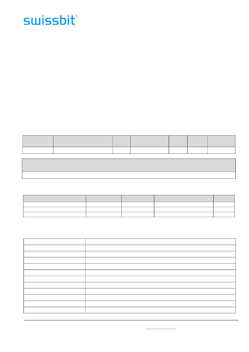
Module Configuration
Organization
256M x 64bit
DDR2 SDRAMs used
16 x 128M x 8bit (1024Mbit)
Row
Addr.
14
Device Bank
Addr.
BA0, BA1, BA2
Column
Addr.
10
Refresh
8k
Module
Bank Select
S0#, S1#
Module Dimensions
in mm
67.60 (long) x 30(high) x 3.80 [max] (thickness)
Timing Parameters
Part Number
SEN02G64C4BF2SA-25[E/W]R
SEN02G64C4BF2SA-30[E/W]R
SEN02G64C4BF2SA-37[E/W]R
Module Density
2048 MB
2048 MB
2048 MB
Transfer Rate
6.4 GB/s
5.3 GB/s
4.2 GB/s
Clock Cycle/Data bit rate
2.5ns / 800MT/s
3.0ns / 667MT/s
3.75ns / 533MT/s
Latency
6-6-6
5-5-5
4-4-4
Pin Name
A0-9, A11 – A13
A10/AP
BA0 – BA2
DQ0 – DQ63
DM0-DM7
DQS0 - DQS7
DQS0# - DQS7#
RAS#
CAS#
WE#
CKE0 – CKE1
S0#, S1#
Swissbit AG
Address Inputs
Address Input / Autoprecharge Bit
Bank Address Inputs
Data Input / Output
Input Data Mask
Data Strobe, positive line
Data Strobe, negative line (only used when differential data strobe mode is enabled)
Row Address Strobe
Column Address Strobe
Write Enable
Clock Enable
Chip Select
Industriestrasse 4
CH-9552 Bronschhofen
Fon: +41 (0) 71 913 03 03
Fax: +41 (0) 71 913 03 15
www.swissbit.com
eMail: info@swissbit.com
Page 2
of 14
发布紧急采购,3分钟左右您将得到回复。
相关PDF资料
SER2LGYRDGNAUEE
SWITCH PUSH SPDT 0.01A 24V
SESD0201C-006-058
ESD PROTECTOR 0201 5.8V SILICON
SESD0201C-120-058
ESD PROTECTOR 0201 5.8V SILICON
SESD0201P1BN-0400-090
TVS DIODE 6V 1CH BI 0201
SESD0402Q2UG-0020-090
TVS DIODE 5V 2CH UNI SMD
SESD0402S-005-054
ESD PROTECT SOD-923 5.4V SILICON
SESD0402X1BN-0010-098
TVS DIODE 5V 1CH BI SMD
SESD0402X1UN-0020-090
TVS DIODE 5V 1CH UNI SMD
相关代理商/技术参数
SEN02G64C4BH2MT-25WR
制造商:SWISSBIT NA INC 功能描述:DDR2 2GB SODIMM 制造商:Swissbit 功能描述:DIMM / SO-DIMM / SIMM 2GB DDR2 SDRAM 64 bit SO-DIMM CL6
SEN-0541
制造商:SENSITRON 制造商全称:Sensitron 功能描述:POWER OPERATIONAL AMPLIFIER
SEN06464H2CH1MT-25R
制造商:SWISSBIT NA INC 功能描述:DDR2 512MB SODIMM
SEN06464H2CH1MT-25WR
制造商:SWISSBIT NA INC 功能描述:DDR2 512MB SODIMM 制造商:Swissbit 功能描述:DIMM / SO-DIMM / SIMM 512MB DDR2 SDRAM 64 bit SO-DIMM CL6
SEN06464H2CH1MT-30R
制造商:SWISSBIT NA INC 功能描述:DDR2 512MB SODIMM
SEN-08501
功能描述:ULTRASONIC RANGE FINDER - LV-MAX 制造商:sparkfun electronics 系列:LV-MaxSonar?-EZ? 包装:散装 零件状态:有效 频率:- 电压 - 额定:5V 光束孔径角:- 工作温度:- 标准包装:1
SEN-08502
功能描述:ULTRASONIC RANGE FINDER - LV-MAX 制造商:sparkfun electronics 系列:LV-MaxSonar?-EZ? 包装:散装 零件状态:有效 频率:42kHz 电压 - 额定:2.5 V ~ 5.5 V 光束孔径角:- 工作温度:- 标准包装:1
SEN-08503
功能描述:ULTRASONIC RANGE FINDER - LV-MAX 制造商:sparkfun electronics 系列:LV-MaxSonar?-EZ? 包装:散装 零件状态:有效 频率:42kHz 电压 - 额定:2.5 V ~ 5.5 V 光束孔径角:- 工作温度:- 标准包装:1
